List of formulae, terms, definitions
| Circumferencial force | Fu | [N] | Lifting force | FH | [N] | |
| Torque | M | [Nm] | Belt length | LB | [mm] | |
| Power | P | [W] | Span length | L1, L2 | [mm] | |
| Mass to be moved | m | [kg] | Number of belt teeth | zB | ||
| Mass of linear slide | mL | [kg] | Number of pulley teeth | z | ||
| Mass of timing belt | mB | [kg] | Number of meshing teeth | ze | ||
| Mass of pulley | mZ | [kg] | Pitch circle diameter | d0 | [mm] | |
| Mass of tension roller | mS | [kg] | Crown diameter | dK | [mm] | |
| reduced mass | mred | [kg] | Tension roller diameter | ds | [mm] | |
| specific weight | ρ | [kg/dm3] | Bore | d | [mm] | |
| Acceleration | a | [m/s2] | Belt width | b | [mm] | |
| Acceleration due to gravity | g | [m/s2] | Pre-tension distance | Δl | [mm] | |
| Speed | v | [m/s] | Specific elasticity | cspez | [N] | |
| Rotational speed | n | [min-1] | Elasticity | c | [N/mm] | |
| Angular speed | ω | [s-1] | ||||
| Centre distance | sA | Positioning deviation | Δs | [mm] | ||
| Usefull linear distance | sL | Positioning range | Ps | [mm] | ||
| total distance of travel | sges | |||||
| Specific tooth force | Ftspez | [N] | Acceleration distance | sB | [mm] | |
| Admissible tensile load | FTzul | [N] | Braking distance | s'B | [mm] | |
| Pre-tension force | FTV | [N] | Inherent frequenc | fe | [s-1] | |
| max. span force | FTmax | [N] | Excitation frequency | f0 | [s-1] | |
| Centre load | FA | [N] | Travel time with v=const. | tv | [s] | |
| Shaft force | Fw | [N] | Overall time | tges | [s] | |
| Frictional force | FR | [N] | Overall distance | sges | [mm] |
Apply all equations with the dimensions mentioned here.
Calculation
\[F_U={2 \cdot 10^3\cdot M \over d_0}\]
Circumferencial force
\[M={d_0 \cdot F_U \over 2 \cdot 10^3}\]
Torque
\[P={M \cdot n \over 9,55 \cdot 10^3}\]
Power
Value to be calculated
circumferencial force FU [N]
torque M [Nm]
power P [kW]
diameter d0 [mm]
\[\omega={\pi \cdot n \over 30}\]
Angular speed
\[n={19,1 \cdot 10^3 \cdot v \over d_0}\]
Rotational speed
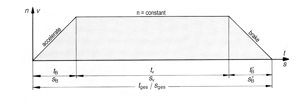
\[v={d_0 \cdot n \over 19,1 \cdot 10^3}={\sqrt {2 \cdot s_B \cdot a \over 1000}}\]
Speed / peripheral speed
\[t_B={v \over a}={\sqrt {2 \cdot s_B \over a \cdot1000}}\]
Acceleration time (braking time)
\[s_B={a \cdot t_B^2 \cdot 10^3 \over 2}={v^2 \cdot 10^3 \over 2 \cdot a}\]
Acceleration distance (braking time)
\[t_v={s_v \over v \cdot 10^3}\]
Travel time when v = const.
\[s_v={v \cdot t_v \cdot 10^3}\]
Travel distance when v = const.
\[t_{ges}={t_B + t_v +t_B}\]
Overall time
\[s_{ges}={s_B + s_v +s_B}\]
Total distance
FU = Acceleration force (1.) + lifting force (2.) + friction force (3.)
= m * a + m * g + m * µ
required circumferencial force at the drive pulley FU [N]
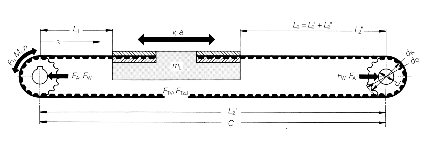
- The acceleration force FB is necessary to accelerate the linear drive with mass m e.g. from the stand still to the limit speed v.
- The lifting force FH is necessary with a movement direction opposite to the acceleration due to gravity. With horizontal linear movement is FH = 0.
- A friction force is required when opposite to the moving direction a force is taking effect, e.g. friction force. Can the frictional drags be neglected is FR = 0.
Calculation
mL [kg] Mass of the linear slide to be moved
mB [kg] Mass of the timing belt (belt weight, see Technical Data)
mZred [kg] reduced mass of pulley(s)
mSred [kg] reduced mass of tension roller(s)
Calculation value
mass to be moved m [kg]
m = mL + mB + mZred + mSre
The mass of a pulley and/or tension roller is calculated in relation to:
\[m_Z={(d_K^2-d^2) \cdot \pi \cdot B \cdot \rho \over 4 \cdot 10^6}\]
\[m_S={(d_S^2-d^2) \cdot \pi \cdot B \cdot \rho \over 4 \cdot 10^6}\]
Mass of the pulley mZ [kg]
Mass of the tension roller mS [kg]
The reduced mass mred of a pulley and/or tension roller is an equivalent mass with equal load bearing to the effective line of the timing belt, the same as the rotational solid to the rotational axis.
\[m_{Zred}={m_Z \over 2 }{[1+{d^2 \over d_K^2}]}\]
\[m_{Sred}={m_S \over 2 }{[1+{d^2 \over d_S^2}]}\]
red. Mass of the pulley mZred [kg]
red. Mass of the tension roller mSred [kg]
A linear drive is pre-tensioned correctly, when under maximum effective circumferencial force FUmax (from acceleration and braking) the slack span side of the belt stayes tight. A minimum pre-tension force is to be considered:
FV ≥ FU
Pre-tension force FV [N]
The highes span forces Fmax are to be expected within the tight span side, when both pre-tension force FV (static) and circumferencial force FU (dynamisch) (dynamic) acting together.
Fmax = FV + FU
maximum span force in the belt Fmax [N]
The permitted tensile load FTzul has to show safety factors to the max. occurring span force Fmax in the timing belt.
(FTzul see Technical Data).
FTzul ≥ Fmax
permitted span force FTzul [N]
The static axis load FAsta act within the stand still or under no-load conditions.
FAdyn is a value depending on the effective circumferencial force.
FAstat = 2 * FV
Axis load [N]
Calculation
\begin{align}
\Delta l&={F_V \cdot L_B \over 2 \cdot c_{spez}}&& \text{Linear slide}\\
\Delta l&={F_V \cdot L_B \over c_{spez}}&& \text{Linear trolley}\\
\Delta l&={F_V \cdot L_B \over c_{spez}}&& \text{Linear table}
\end{align}
Calculation value
pre-tension distance Δl [mm]
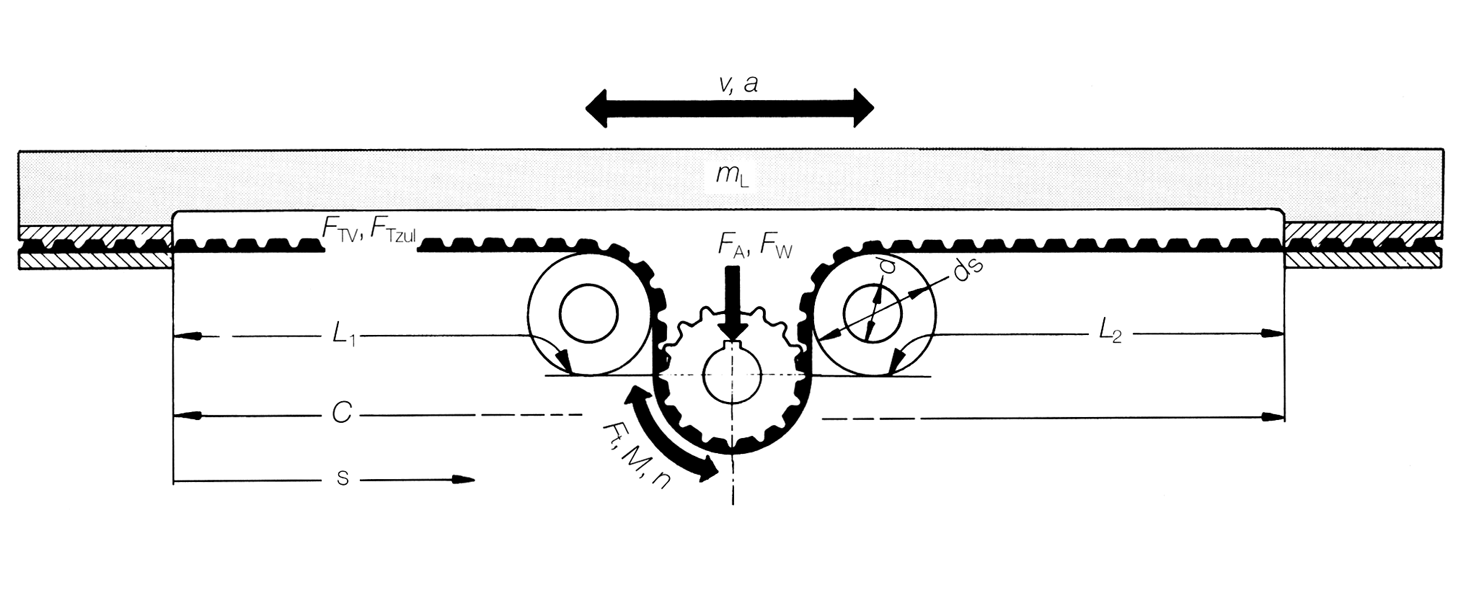
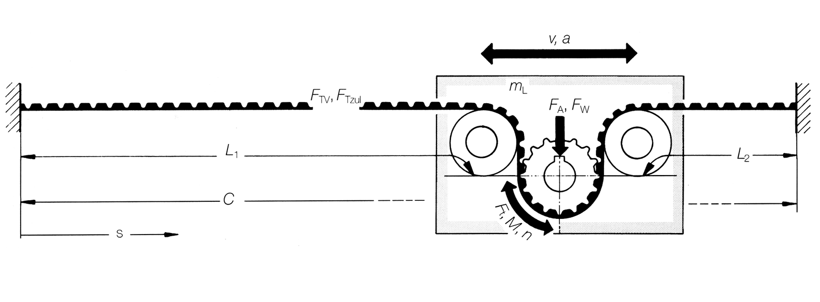
The tensioning station can be mounted at any position on the timing belt.
Values for cspez see Technical Data.
\[c={{L_B \over L_1 \cdot L_2}\cdot c_{spez}}\]
Elasticity c [N/mm]
\[L_B={L_1 + L_2}\]
Linear systems show a variable elasticity. The elasticity behaviour of the linear slide and/or linear bed depends on the length proportion L1 and L2.
That means: Each individual position of the linear bed has its own elasticity.
The elasticity shows a minimum cmin, when L1 and L2 are equal in length. For this case the following relation is valid:
\[c_{min}={4 \cdot c_{spez} \over L_B}\]
for L1=L2
Is an external force acting on a linear slide a positioning deviation s results from the relation:
\[\Delta s={F \over c}\]
Positioning deviation Δs [mm]
Under the effect of a triggered force, a mass connected to the timing belt (elasticity/mass system) assumes a damped natural vibration.
\[f_e={{1 \over 2\pi}\sqrt{c \cdot 1000 \over m_L}}\]
Natural frequency fe [s-1]
If necessary, check linear drives with regard to the occurrence of excitation frequencies f0 in the drive pulley assembly which are close to the natural frequency fe.
For technical structures, avoid compatibility of fe = f0< (Resonanz) (resonance).
Note: In linear drives, the natural frequency fe is in general considerably higher than the excitation frequency f0 of the drive, in which case no resonance is to be expected . We recommend a special examination, if necessary, where stepping motors are used. Measures in the event of resonance: Increase the stiffness of the timing belt by choosing a larger belt width.
How to proceed
The above mentioned equations can be used to comprehensively compute BRECO linear drives. The type of the individual examinations depends on the task. If necessary, request technical support from our sales outlets.
General kinematics
If the movement sequence of the linear drive has to be timed, we recommend to proceed in accordance with the linear movement values of the equations (3).
Coarse design according to mass and acceleration
Generally, the mass of the linear slide mL and the acceleration a represent the decisive values for the design of linear drives. The selection diagram, the belt type and timing belt width can be determined, based on mass and acceleration shown on the page Determination of belt type and belt width.In conjunction with the coarse design, we recommend to adopt the pulley dimensions (as a provisional measure). Note the permissible minimum number of teeth or minimum diameters.
Drive pulley assembly
The required circumferential force FU in the drive pulley assembly has to be determined according to equation (4). By provisionally assuming the pulley size, it is possible to calculate the attendant drive torque M according to equation (2) for the drive pulley assembly. In how far the calculated torque M can be harmonised with the torque sequence of the motor, depends on the type and selection of the drive motor. The selection of the motor also depends on the desired servo and positioning tasks. Once the drive motor has been decided upon, the actual torque sequence of the motor has to be taken into consideration for the further precise design of the timing belt.